


A waterfall shows the frequency spectrum of 100Hz to 2000Hz. Just slide the waterfall slide on a PSK carrier frequency and DroidPSK and decode the signal. In transmitting mode characters can be entered trough the keyboard. 9 Macros are also available to store standard texts like “name and qth” and “station info”

Starting V2.0 Droid PSK also now includes a logbook. Callsign, Name RST etc can be easily tranfered into the lookbook from the receiving screen.
The logbook also includes ADIF export and import to transfer your logbook data to a PC based logging software.
DroidPSK to FT817 Interface
This is a small interface which makes it possible to connect an Android cell phone or tablet to a FT- 817. This circuit might work on other radios as well but I was only able to test it on a FT817 and an IC756PROII. The goal was to build an interface which doesn’t need an external power supply. Since the Android device doesn’t have a serial port to switch the PTT another solution had to be found. After some research on the internet I found a nice schematic from KH6TY (https://sites.google.com/site/kh6tyinterface/ ) .
I built the board but all the available Android cell phones and tablets (Droid Incredible, Dell Streak 7 and Motorola Xoom) only provided about 200mVss audio output which is not enough to switch a transistor. An audio 16:500 audio transformer was the solution. I got more than 1 Vss out of the transformer. The rectified signal switched the transistor.
The audio input of the Android device was another problem. When connecting the phone directly to the isolation transformer I had the problem that the phone didn’t recognize the external audio signal or the music player all of a sudden started up. I did some measurements on a headset which I sometimes use with my phone and I had conductivity in one direction but not in the other. It looked like a transistor needed to be connected to the audio input. I am not sure about the value of the resistor R9. 5.6K worked very well on all my testing devices. But depending on the voltage the phone provides on the external microphone pin the value might be different.
Here is the schematic I came up with:
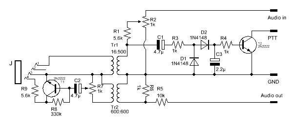
Component list
C1 = 4.7µ
C2 = 4.7µ
C3 = 2.2µ
D1 = 1N4148
D2 = 1N4148
J =3.5mm 4 pin (Mouser 171-7435-EX)
R1 = 5.6k
R2 = 1k (variable)
R3 = 1k
R4 = 1k
R5 = 10k
R6 = 1k
R7 = 1k (variable)
R8 = 330k
R9 = 5.6k
T1 = 2N2222
T2 = 2N2222
Tr1 = 16:500 (42TM026-RC)
Tr2 = 600:600
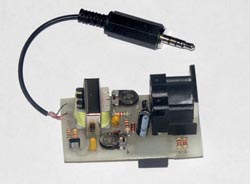
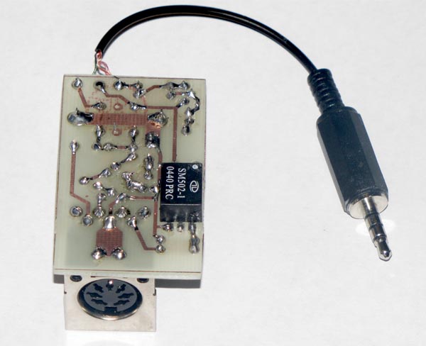
The first prototype looks like this:

Update: I tested the interface with an ICOM IC756PRO II and it worked fine. I think this interface will work with most radio as long as there is a small voltage present at the PTT pin. I am more concerned that the interface will not work with all Android devices. On my Droid Incredible I need to set the volume to at least the second highest level to get the PTT to switch. If the audio level is to low on the Android device the interface might now work.
If you have any suggestions or questions please email me at info@wolphi.com. I would like to hear from you.
This schematic is without any warranty. It worked on my phones and my FT817 but I can not guarantee that it will work with all the Android devices. Please test this schematic at your own risk. I can not be held responsible if you damage your phone or radio.
I have made this circuit as a dead bug and it works well.
ReplyDelete