

i have successfully uploaded my home made video for Morse code.
It is an audio material on how to learn Morse code.
Enjoy the video and dont forget to share it with your family and friends.
Popular Posts
-
 Having Space Constraint At Your QTH To Put Up An Antenna For HF Band?. Then Try Constructing This Magnetic Loop Antenna. D...
 -
 There is calculator for building magnetic loop antenna. Try this calculator, to see hows the performance before making you own magnetic loop...
 -
 Maybe some of us are regretting about their ISP ( Ex: Celcom broadband in Malaysia ) blocking ports for Echolink. This method also applicabl...
 -
DroidPSK is an app for Android to decode and encode Ham Radio BPSK31 with the build in microphone/speaker or wired to your radio. A waterf...
Wednesday, May 25, 2011
Sunday, May 22, 2011
Sejarah Radio Amatur Indonesia
Amatir Radio
 Sekilas Sejarah Amatir Radio di Indonesia
Kegiatan Amatir radio merupakan kegiatan orang-orang yang mempunyai hobby dalam bidang tehnik transmisi radio dan elektronika, kegiatan ini disahkan, diatur dan diawasi secara global baik oleh Badan-badan telekomunikasi international seperti ITU dan IARU maupun oleh badan telekomunikasi nasional disetiap negara.
Oleh karena itu dalam melakukan kegiatannya mereka mempunyai dan berlandaskan KODE ETIK AMATIR RADIO. Kegiatan amatir radio di Indonesia dimulai pada tahun 1930-an ketika Indonesia masih dalam jajahan Belanda atau Hindia Belanda. Sangat sedikit orang yang dipercaya oleh kekuasaan untuk memiliki izin amatir radio saat itu. Dua diantara mereka yang disebut-sebut sebagai pelopor adalah : Rubin Kain (YB1KW) yang izinnya didapat tahun 1932. Beliau telah meninggal pada tahun 1981. Yang kedua adalah B. Zulkarnaen (YB0AU) yang izinnya didapat pada tahun 1933. Beliau juga telah meninggal pada tahun 1984.
Semua aktifitas amatir radio dihentikan pada saat pendudukan Jepan dan Perang Dunia II, namun ada dari sebagian mereka yang tetap nekat beroperasi dibawah tanah untuk kepentingan Revolusi Kemerdekaan Republik Indonesia. Tahun 1945, proklamasi kemerdekaan RI disiarkan ke seluruh dunia dengan menggunakan sebuah pemancar radio revolusioner yang dibuat sendiri oleh seorang amatir radio yang bernama Gunawan (YB0BD). Jasa YBoBD ini diakui oleh Pemerintah dan sebagai penghargaannya, pemancar radio buatan Gunawan tersebut di simpan di Museum Nasional Indonesia. Selanjutnya, kegiatan amatir radio diselenggarakan kembali pada tahun 1945 sampai dengan 1949.
Namun karena alasan keamanan dalam negeri, pada tahun 1950, pemerintah melarang kegiatan amatir radio hingga tahun 1967. Landasan pelarang itu adalah Undang-undang No. 5/1964 yang menegaskan hukuman yang sangat berat bagi mereka yang memiliki pemancar radio tanpa izin. Pada tahun 1966, amatir radio memperjuangkan kepentingannya kepada pemerintah agar amatir radio dapat diselenggarakan kembali di Indonesia. Akhirnya, dengan Peraturan Pemerintah No. 21/1967, pemerintah mengizinkan kembali kegiatan amatir radio.
Melalui Konferensi Amatir Radio yang pertama pada tgl. 9 Juli 1969 di Jakarta, didirikan organisasi yang bernama Organisasi Radio Amatir Republik Indonesia (ORARI). Pada Munas ORARI tahun 1977, nama organisasi dirubah menjadi Organisasi Amatir Radio Indonesia dengan singkatan yang sama hingga sekarang. Terbentuknya ORARI dapat dikatakan berawal di Jakarta dan Jawa Barat atau pulau Jawa pada umumnya dan diprakarsai oleh kegiatan aksi mahasiwa, pelajar dan kaum muda, diawal tahun 1965 sekelompok mahasiwa publistik yang tergabung dalam wadah KAMI membentuk radio siaran perjuangan bernama Radio Ampera, mulai saat itu juga bermunculanlah radio siaran lainya seperti Radio Fakultas Tehnik UI, Radio Angkatan Muda, Kayu Manis, Draba, dll. Sudah tentu semua radio siaran itu merupakan siaran yang tak memiliki izin alias Radio gelap.
Sadar karena semakin banyaknya radio siaran bermunculan yang memerlukan suatu koordinasi demi tercapainya perjuangan ORBA maka dibentuklah pada tahun 1966 oleh para mahasiwa suatu wadah yang diberi nama PARD (Persatuan Radio Amatir Djakarta) diantaranya terdapat nama-nama koordinatornya seperti Willy A Karamoy. Ismet Hadad, Rusdi Saleh, dll. Di Bandung juga terbentuk PARB. Bagi anggota yang hanya berminat dalam bidang teknik wajib menempuh ujian tehnik dan bagi kelompok radio siaran disamping perlu adanya tehnisi yang telah di uji juga wajib menempuh ujian tehnik siaran dan publisistik.
Setelah itu kesemuanya diberi callsign menggunakan prefix X, kode area 1 s/d 11 dan suffix 2 huruf sedangkan huruf suffix pertamanya mengidentifikasikan tingkat keterampilannya A s/d F seperti X6AM, X11CB dsb sedangkan untuk radio siaran diberi suffix 3 huruf. Pada mulanya PARD merupakan wadah bagi para amatir radio dan sekaligus radio siaran . Sehingga pada saat itu secara salah masyarakat mengidentikan Radio amatir sebagai radio siaran non RRI.
Karena adanya tingkatan keterampilan, PARD saat itu juga menyelenggarakan ujian kenaikan tingkat. Disamping itu terdapat juga para Amatir era 1945-1952 yang tergabung dalam PARI (Persatoean Amatir Repoeblik Indonesia 1950), diantaranya terdapat nama – nama , Soehodo . (YBØAB), Dick Tamimi . (YBØAC), Soehindrio (YBØAD), Agus Amanto (YBØAE), B. Zulkarnaen . (YBØAU), Koentojo (YBØAV) dll. Diantara mereka ternyata ada juga yang menjadi anggota PARD seperti, (YBØAE) dan (YBØAU). – Doc RRI-.
posted by yc2www di http://7070mhz.wordpress.com/amatir-radio/
Wednesday, May 18, 2011
NVIS communications in the HF band
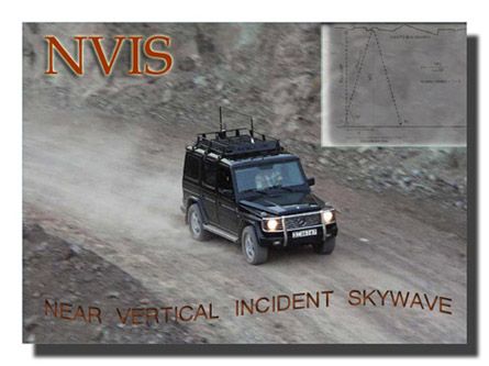
NVIS communications in the HF band
Fundamentals of the propagation using near vertical incident skywave (NVIS) in the HF band, describing the geometry of the circuits and how to select the appropriate operative frequencies. Some notions about NVIS antennas for base and operations on the move are also provided.
1. Introduction.
It is a normal practice in HF radio communications to look after medium or long range (DX) links using ionospheric propagation. In order to achieve this, operators use antennas with radiation patterns having a very low takeoff angle, in the range around 3 degrees, and frequencies in any band below the maximum usable frequency (MUF) for a given distance. The low takeoff angles cause the first ionospheric reflection to be produced at long distances from the transmitter station, increasing the range of communications, with the drawback of the existente of a shadow zone or skip zone where the transmission will not be received, at least from the point where the ground wave vanishes.For short range communications, the VHF and UHF bands are used, and the radio waves are affected by reflection, multipath propagation, refraction and diffraction, being the radio coverage from about 10 km up to about 60 km, depending on the type of terrain, the antennas used and the transmission power. In order to increase this communications range, repeater stations are used.
Therefore we find a shadow zone which may not be covered neither with the VHF and UHF short range radios nor with the HF radios with their special antenna characteristics, normally designed for DX operations. There is also the possibility of a VHF/UHF repeater failure which may degrade the radio coverage in an undesired way.
The coverage of this skip zone may be extremely important in cases of emergency operations, so it is of particular interest to develop radio systems capable of providing communications in this area. In order to achieve this, we can use a HF propagation mode called NVIS (Near Vertical Incident Skywave), thoroughly used during the Second World War and unknown to a vast number of users of the HF bands.
Working in NVIS can be achieved with the traditional HF radios. As we will see, there are only two considerations to be aware of:
- Choosing an adequate working frequency.
- Using an antenna with NVIS radiation pattern.
2. NVIS propagation fundamentals.
The NVIS propagation is based in the use of antennas with a very high takeoff angle, in the range from 70 to 90 degrees, that is, perpendicular or near perpendicular to the ground plane. When transmitting in HF with an antenna like that and choosing an adequate frequency, the radio wave will come into contact with the ionosphere in a near vertical angle and will be reflected towards the ground with a very low reflection angle, making possible to cover the skip zone of the HF DX systems, which is neither covered by the VHF/UHF systems.For instance, we will suppose a NVIS antenna whose main radiation lobe is located between 70 and 90 degrees of elevation over the ground plane. We will support our analysis with the draw shown in the figure 1.
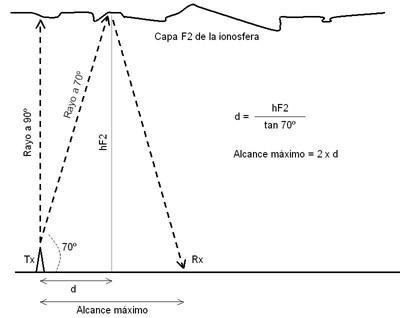
Fig.1. Diagram of a NVIS radio link
The NVIS antenna radiates in the whole region between 70 and 90 degrees of elevation. With the first reflection on the ionosphere, which takes place in the F2 layer, the radio coverage area will spread from the transmitter station to a maximum reach point which may be calculated using trigonometry.
We do know the takeoff angle which provides the maximum range, being 70 degrees. The distance "d" is unknown, but we know that it is the half part of the maximum range. In order to solve the equation, we need a second data: the height at which the reflection in the F2 layer takes place. This height, named "hF2", is being continuously measured by ionosonde stations spread all around the world and is subject to variations mainly with the hour of the day. In the figure 2, it is shown the data collected by the ionosonde station located at the Ebro Observatory (Tarragona, Spain), during September, 27th, 2008. Click on the image to zoom.

Fig.2.Mediciones de la frecuencia crítica y de la altura de la capa F2.
In order to provide an estimation of our coverage range, we will consider the two extreme values of hF2 during this day, being around 150 km of height at night and 310 km during the day. At night, the ionosphere F1 and F2 layers are merged in the F layer, which also allows NVIS communications.
If we put those values in the formula shown in the figure 1, we will have maximum ranges between 110 km and 225 km. Depending on the period of time taken into account, the height hF2 may reach up to 400 km, providing radio coverages of up to 300 km, considering an antenna with the indicated takeoff angles.
That is, our NVIS system allows to establish HF communications in a range of up to 300 km around the transmitter station, or even longer, without skip zones. This kind of communications are usually established with only one ionospheric hop and the required power levels are low, normally being enough with 20 W or even less.
3. How to choose the working frequency.
The selection of an appropiated working frequency is essential for a successful operation in NVIS. As a general rule, we will choose a frequency 10% below the ionosphere's F2 layer critical frequency (foF2) at a given time.It is of particular importance not to confuse the foF2 with the MUF. The critical frequency foF2 is the maximum frequency that a radio wave can have in order to be reflected in the F2 layer when arriving at this layer with an angle of incidence of 90 degrees (perpendicular). In the MUF, angles of incidence different of 90 degrees are considered, which practically means that a different MUF will exist for each distance of a HF radio link.
Our goal now is to get foF2 forecasts or, much better, real time measurements of the foF2 made with an ionosonde nearby our transmitter station at a close time. Let's not forget that the foF2 has significant changes over the day and also that it will be different depending on the transmitter location.
In order to get this data, we can check the web site of the Mass Lowel University Center for Atmospheric Research (Massachussetts, USA), where there is a record of foF2 values (among other parameters) measured by ionosondes all around the world.
http://ulcar.uml.edu/stationmap.html
For the particular case of Spain, there are two ionosonde stations offering data to the public, one located at the Ebro Observatory (Roquetes, Tarragona) and the other at the National Institute for Aerospace Technology facilities at El Arenosillo (Huelva).
Ionosonde stations provide special graphs named ionograms, as the one shown in the figure 3. Click on the image to zoom.
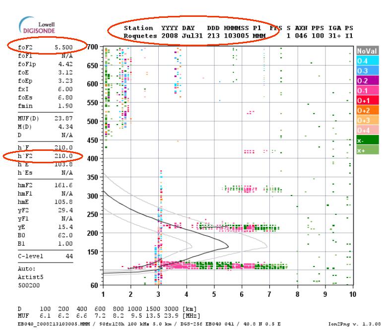
Fig.3. How to pick up the critical frequency foF2 from an ionogram.
In the upper part of the ionogram we can check the hour and date of the measurement, being in the example "2008 Jul31 103005", that is, 31st July 2008 at 10:30 UTC.
In the same upper part, on the left we can see the measured value of the foF2 at this particular time, being 5,500 MHz in the example. If we want to evaluate our communications range, we can read also the value of the height hF2, being 210 km in the example.
Putting into practice our 10% rule, if the foF2 has a value of 5,500 MHz, our NVIS optimal working frequency will be 4,950 MHz at this particular time of day.
Once completed the calculations, we may have the problem of not being authorized to transmit in this particular frequency, as it may occur within the Amateur Radio Service, or even that this frequency is already in use by other stations or with high noise or interference level. In this cases, we will choose a frequency of an authorized band just below the calculated frequency and as near as possible. Never select a frequency above the foF2 because there will not be ionospheric reflection.
4. NVIS antennas.
Apart from choosing a proper working frequency, the other critical point is having an antenna with NVIS capabilities, that is, having a radiation pattern with a main lobe between 70 and 90 degrees of elevation over the ground plane.One possible option is to purchase an antenna especially designed for NVIS, but it is necessary to take into account that such models are normally manufactured for military use only.
Other interesting option is to take advantage of some of the antennas that we normally use for DX communications in HF.
4.1. Base station antennas.
There are a lot of antenna designs to work in NVIS. We will focus in the simpler NVIS antenna for base stations or field operations ever built: the horizontal dipole (figure 4). The same dipole we use for DX. As we will see, the key factor is the height at which we must install the dipole over the ground.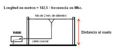
Fig.4. Horizontal wire dipole.
The radiation pattern of an horizontal wire dipole is different as a function of its distance to the ground plane, something which may be easily checked with simulation software such as NTIA/ITS HFAnt.
In the hypothetical and theoretical case of having a dipole installed at one wavelength over ground (at a height of 43 meters if the dipole is for the 7 MHz band), the radiation pattern in elevation will be as the one shown in the figure 5, presenting two main radiation lobes with low takeoff angles. Click on the image to zoom.

Fig.5. Horizontal dipole placed a one wavelength over the ground.
If we put the dipole down to a more appropiate height over ground for installation purposes, let's say to a quarter of the working wavelength (10 meters for a dipole cut for 7 MHz), the radiation pattern in elevation will show one main lobe with its maximun gain located at a takeoff angle of 49 degrees, as shown in the figure 6. The radiation perpendicular to the ground plane is also good, so this installation could be used for NVIS operations. Click on the image to zoom.

Fig.6. Horizontal dipole placed a one quarter wavelength over the ground.
If we continue performing tests and we place the dipole lower and lower, we will check that the radiation pattern rises, up to a point at an exact height of the dipole of one tenth of the working wavelength (4 meters for a dipole for 7 MHz), where the radiation maximum is located at a takeoff angle of 90 degrees, perpendicular to the ground plane, as shown in the figure 7.
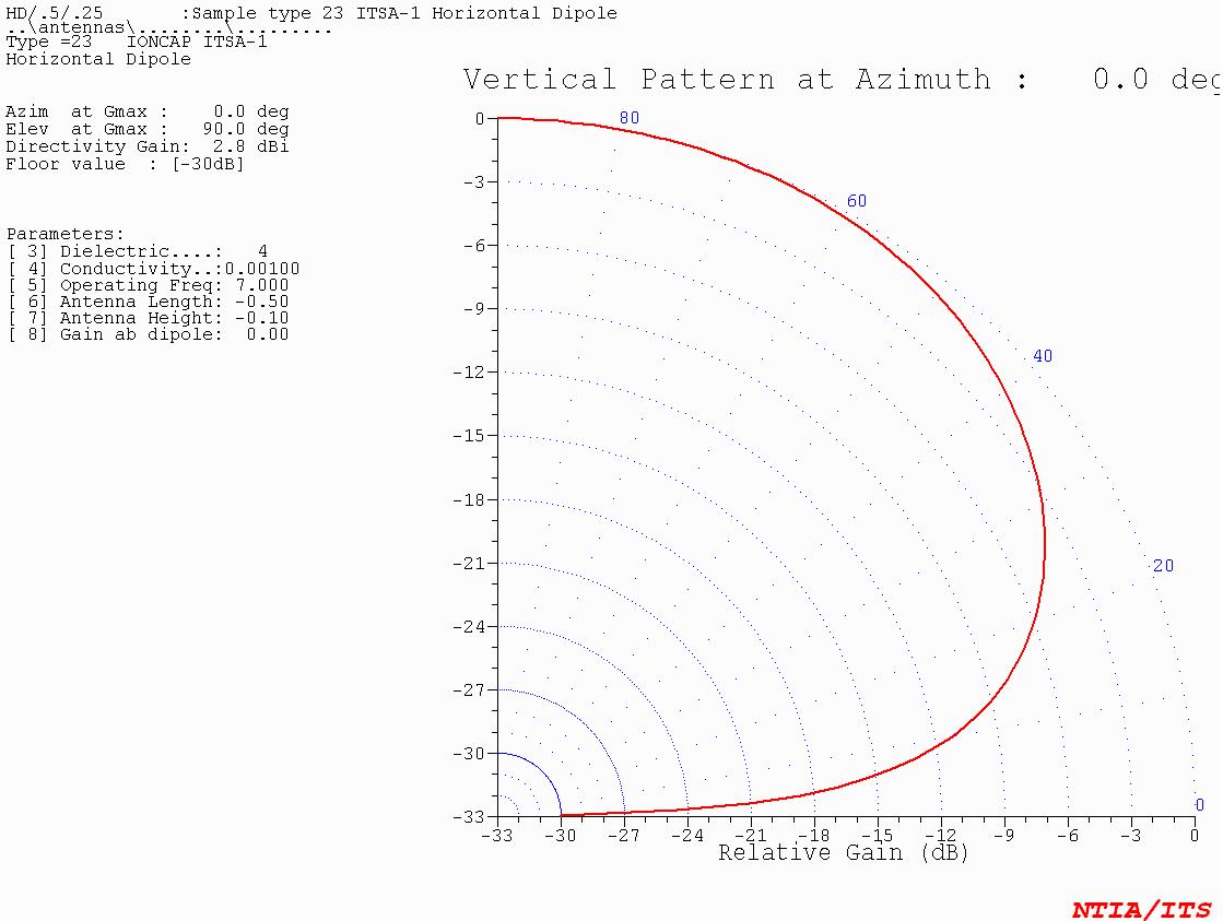
Fig.7. Horizontal dipole placed a one tenth wavelength over the ground.
If we consider the -3 dB bandwidth, our dipole will be radiating mainly between 30 and 90 degrees in elevation, making this configuration ideal for NVIS operations.
If we continue lowering the dipole, the effect is that the radiation pattern will be more and more high and narrow, losing effectivity in the direction perpendicular to the ground plane. One possible solution should be installing a second conductor wire near the ground plane, as a reflector.
Obviously, the electrical conductivity of the terrain will also have an influence in our antenna. Some authors state that the better distance over the ground to place the dipole is between 0,15 and 0,25 times the working wavelength.
In the design process of a NVIS antenna, we need to take into account that, besides the imposed need of radiating as much vertical as possible, we need to avoid secondary radiation lobes at low takeoff angles due to the fact that they may generate a ground wave of enough intensity to interfere with the reflected skywave in areas near the transmitter station.
4.2. Antennas for mobile communications.
For mobile communications, that is, with the HF radios installed in vehicles, we have two options.The quickest option is using a common vertical antenna and bend it until it is parallel to the ground plane. It will be difficult to achieve the required distance to this plane, but an approximation could provide radiation patterns good enough to work in NVIS.
The other option is having an antenna specifically designed for NVIS. One of the most used antennas for this purpose is the magnetic half-loop, which can be installed on the roof of a vehicle. In the figure 8 a diagram of this type of antenna is shown, designed with the software MMANA-GAL.
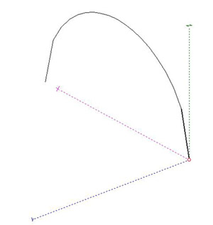
Fig.8. NVIS half-loop antenna.
Those antennas are normally fed from the transceiver by one of its ends and have the peculiarity of having the other end connected to ground. This way, a virtual full loop is built, whose behaviour is mainly magnetic. The radius of the arch is around 1,5 meters.
The great advantage with respect to other NVIS antennas is that the half-loop has an omnidirectional radiation pattern, as shown in the figure 9, making this antenna quite convenient for communications on the move.
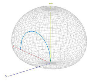
Fig.9. Radiation pattern of a half-loop NVIS antenna.
Another great advantage is the magnetic behaviour, quite similar to the one of the full loop antennas, providing a high Q factor which helps to minimize noise and interferences.
However, this kind of antennas has two important problems: first, the radiation pattern is no more as the one shown in the figure when installing the antenna on top of a vehicle, being distorted mainly backwards, and in the other hand it may have a very high capacitive impedance which may be difficult to match at some frequencies. Besides, the efficiency of radiation is quite low and the antenna has a negative gain (losses).
5. Conclusions.
NVIS communications allow to establish radio links in the HF bands at ranges of up to 300 km without shadow areas, covering the gap existing between the maximum range of VHF/UHF systems and the skip zone of the first hop in DX communications in the HF band. This fact makes NVIS a suitable mode for emergency operations, being its use quite extensive both in those environments and among the military.In order to operate in NVIS we must take into account two fundamental premises. First, we need to choose an adequate antenna with a radiation pattern of enough elevation, such as a horizontal dipole placed at a height over ground of about one tenth of the working wavelength. It is also necessary to select the proper working frequency, always below the critical frequency of the ionosphere's F2 layer (foF2) and in an optimum way around 10 % below it.
Ismael Pellejero - EA4FSI
original article: http://www.ipellejero.es/hf/NVIS/english.html
FCC Issues or Upholds Nearly $70,000 in Pirate Fines

The FCC is clearing its decks, so to speak, of pirate fines.
In two days, the commission has announced or upheld a total of $67,000 in fines to four people for operating unlicensed radio stations in separate cases, and it issued another $4,000 proposed fine to one ham operator for using an unauthorized frequency.
Two Boston-area cases progressed to the level of forfeiture orders because the FCC says neither Robert Brown nor Lloyd Morris responded to Notices of Apparent Liability for $15,000 each. The notices were issued to Brown and Morris in October of 2010. They have 30 days to pay or the FCC says it may turn the cases over to the Justice Department for collection.
The next two cases occur in Florida. The FCC decided Fritzner Lindor is apparently liable for a $15,000 fine after Tampa office agents traced an unauthorized signal operating on 94.7 MHz in Orange Park to his home. During an inspection in June of 2010, the commission says he admitted he bought a transmitter and operated the station without a license. Involved in broadcasting for 19 years, he knew his actions violated the Communications Act, according to the agency. He has 30 days to appeal or pay.
In the second Florida case, the commission issued a proposed fine to Judith V. Smith of $22,000 for operating an unlicensed radio transmitter on 95.9 MHz in Miami, and for refusing to allow FCC agents to inspect the station, located in her home. “Gospel Reggae FM” also has a website named “Gospel Reggae FM.com.” In June of 2010, agents traced an unauthorized signal to her home. They say she opened the door, identified herself and refused to let them in. She then closed the door and turned off the transmitter. She has 30 days to appeal.
Finally, another fine is in a ham radio case. The commission affirmed a proposed fine of $4,000 against Jose Torres for operating his amateur station on an unauthorized frequency, 26.71 MHz. Torres is the licensee of Amateur Extra Class station N3TX in Philadelphia. The agency says he’d been warned about not operating on that frequency and fined $4,000 in 2009. He asked that the fine be reduced or cancelled, telling agents he wasn’t home during the alleged unauthorized operations in 2008 and submitted cellphone records to support his claim; Torres also submitted three years of federal tax returns to bolster his argument of an inability to pay. The FCC didn’t buy his arguments; field agents say they heard his voice on the unauthorized transmissions and that the cellphone records don’t prove he wasn’t at home, only that he wasn’t using his landline at the time.
Federal Communications Commissionhttp://www.radioworld.com/article/fcc-issues-or-upholds-nearly-70000-in-pirate-fines/23519
Washington, D.C. 20554
)
)
In the Matter of
) File Number EB-08-PA-0180
Jose Torres
) NAL/Acct. No. 200932400002
Licensee of Station N3TX
) FRN 0001-83-1825
Philadelphia, Pennsylvania
)
)
NOTICE OF APPARENT LIABILITY FOR FORFEITURE
Released: January 6, 2009
By the District Director, Philadelphia Office, Northeast Region,
Enforcement Bureau:
I. INTRODUCTION
1. In this Notice of Apparent Liability for Forfeiture ("NAL"), we find
that Jose Torres ("Torres"), the licensee of Amateur Extra Class
Station N3TX in Philadelphia, Pennsylvania, apparently willfully and
repeatedly operated his amateur station on an unauthorized frequency,
in violation of Section 1.903(a) of the Communications Act of 1934,
as amended ("Act"). We conclude, pursuant to Section 503(b) of the
Communications Act of 1934, as amended ("Act"), that Torres is
apparently liable for a forfeiture in the amount of four thousand
dollars ($4,000). We also admonish Jose Torres for failing to transmit
his call sign, in violation of Section 97.119(a) of the Rules.
II. BACKGROUND
2. On December 11, 2007, in response to a complaint of interference to
over-the-air television reception, agents from the FCC's Philadelphia
Office drove to the complainant's residence and began monitoring the
frequencies in and around the Citizens Band (CB) from 26.965 MHz to
27.405 MHz. Between approximately 6:50 p.m. and 7:10 p.m. and between
approximately 8:40 p.m. and 9:00 p.m. that evening, the agents
observed transmissions on the frequency 26.71 MHz. The agents
contacted the complainant and confirmed that the harmful interference
to the television reception was occurring during the times when the
agents observed the transmissions on 26.71 MHz. The agents used
direction finding techniques and identified the source of the signal
on 26.71 MHz as Jose Torres's residence, which is located in close
proximity to the complainant's residence in Philadelphia,
Pennsylvania. The agents did not observe any station identification
announced during the radio transmissions on 26.71 MHz.
3. On December 11, 2007 at 9:10 pm, the agents inspected the radio
station located at Torres's residence. When the agents arrived, they
observed that Torres's radio transmitting equipment was turned off.
When Torres turned the radio transmitting equipment on, the agents
observed that it was tuned to the frequency 26.71 MHz. During the
inspection, Torres claimed that he was not transmitting on the
frequency 26.71 MHz but he was listening to the Spanish conversation
on 26.71 MHz. Torres also informed the agents that he holds an Amateur
Extra Class License under the call sign N3TX. The agents informed
Torres that the Amateur Extra Class License does not authorize him to
operate on 26.71 MHz and that he must cease all transmissions on 26.71
MHz immediately.
4. On January 7, 2008, the Philadelphia Office issued Jose Torres a
Notice of Violation for operating on an unauthorized frequency, in
violation of Section 1.903(a) of the Rules, and for failing to
transmit the call sign identification, in violation of Section
97.119(a) of the Rules. On February 6, 2008, and February 8, 2008, the
FCC Philadelphia Office received two separate letters of similar
content from Jose Torres, in response to the Notice of Violation. In
his responses, Torres stated "[w]ith this writing respond I agree to
the Notice listed above. I fully understand the violation. According
to my license N3TX I will transmit where I'm authorized, at the Extra
Class portion only."
5. On February 15, 2008, the FCC Philadelphia Office received an e-mail
from the complainant alleging that the harmful interference to the
television has reappeared and is affecting the reception of
over-the-air television programming.
6. In response to a complaint that the interference had returned, agents
initiated another investigation. On April 17, 2008, between 8:00 pm
and 9:30 pm and on June 2, 2008 between 3:00 pm and 3:40 pm, agents
from the FCC's Philadelphia Office monitored and recorded radio
transmissions on the frequency 26.71 MHz. The agents used direction
finding techniques to locate the source of the transmission on 26.71
MHz to Torres's residence. At no time did Torres identify his
communications by transmitting his Amateur station call sign N3TX.
III. DISCUSSION
7. Section 503(b) of the Act provides that any person who willfully or
repeatedly fails to comply substantially with the terms and conditions
of any license, or willfully or repeatedly fails to comply with any of
the provisions of the Act or of any rule, regulation or order issued
by the Commission thereunder, shall be liable for a forfeiture
penalty. The term "willful" as used in Section 503(b) of the Act has
been interpreted to mean simply that the acts or omissions are
committed knowingly. The term "repeated" means the commission or
omission of such act more than once or for more than one day.
8. Section 1.903(a) of the Act states that stations in the Wireless Radio
Services must be used and operated only in accordance with the rules
applicable to their particular service as set forth in this title and
with a valid authorization granted by the Commission. On December 11,
2007, Torres operated radio transmitting equipment from his residence
on 26.71 MHz. The license for station N3TX authorizes Jose Torres to
operate on specific frequencies in the Amateur Radio Service Band, but
does not authorize Jose Torres to operate 26.71 MHz. During a December
11, 2007, inspection the agents warned Torres that he must immediately
cease operating on the frequency 26.71 MHz. Furthermore, in the
January 7, 2008, Notice of Violation, the Philadelphia Office notified
Torres that he was in violation of Section 1.903(a) of the Rules for
operating on the unauthorized frequency. Notwithstanding these
warnings, on April 17, 2008, and June 2, 2008, Commission agents
determined that Torres operated radio transmitting equipment from his
residence on the frequency 26.71 MHz. Because Torres operated his
Amateur Radio station on an unauthorized frequency after being warned
that he did not have authority to do so and because he admitted to
such unauthorized operation, we find that the violation was willful.
Because the violation occurred on more than one day, it was repeated.
9. Pursuant to The Commission's Forfeiture Policy Statement and Amendment
of Section 1.80 of the Rules to Incorporate the Forfeiture Guidelines,
("Forfeiture Policy Statement"), and Section 1.80 of the Rules, the
base forfeiture amount for operating radio transmitting equipment on
an unauthorized frequency is $4,000. In assessing the monetary
forfeiture amount, we must also take into account the statutory
factors set forth in Section 503(b)(2)(E) of the Act, which include
the nature, circumstances, extent, and gravity of the violations, and
with respect to the violator, the degree of culpability, and history
of prior offenses, ability to pay, and other such matters as justice
may require. Applying the Forfeiture Policy Statement, Section 1.80 of
the Rules, and the statutory factors to the instant case, we conclude
that Jose Torres is apparently liable for a ($4,000) forfeiture.
10. Section 97.119(a) of the Commission's Rules states that each amateur
station, except a space station or telecommand station, must transmit
its assigned call sign on its transmitting channel at the end of each
communication, and at least every 10 minutes during a communication,
for the purpose of clearly making the source of the transmissions from
the station known to those receiving the transmissions. On December
11, 2007, April 17, 2008, and June 2, 2008, agents from the
Philadelphia Office observed that Torres did not transmit his call
sign N3TX while operating his Amateur Radio station on the frequency
26.71 MHz. Based on the evidence before us, we admonish Jose Torres
for willfully and repeatedly violating Section 97.119(a) of the Rules
for failing to transmit a call sign.
IV. ORDERING CLAUSES
11. Accordingly, IT IS ORDERED that, pursuant to Section 503(b) of the
Communications Act of 1934, as amended, and Sections 0.111, 0.311,
0.314 and 1.80 of the Commission's Rules, Jose Torres is hereby
NOTIFIED of this APPARENT LIABILITY FOR A FORFEITURE in the amount of
four thousand dollars ($4,000) for violation of Section 1.903(a) of
the Act.
12. IT IS FURTHER ORDERED that Jose Torres IS ADMONISHED for willfully and
repeatedly violating Section 97.119(a) of the Commission's Rules.
13. IT IS FURTHER ORDERED that, pursuant to Section 1.80 of the
Commission's Rules within thirty days of the release date of this
Notice of Apparent Liability for Forfeiture, Jose Torres SHALL PAY the
full amount of the proposed forfeiture or SHALL FILE a written
statement seeking reduction or cancellation of the proposed
forfeiture.
14. Payment of the forfeiture must be made by credit card through the
Commission's Revenue and Receivables Operations Group at (202)
418-1995, or by check or similar instrument, payable to the order of
the Federal Communications Commission. The payment must include the
Account Number and FRN Number referenced above. Payment by check or
money order may be mailed to Federal Communications Commission, P.O.
Box 979088, St. Louis, MO 63197-9000. Payment by overnight mail may be
sent to U.S. Bank - Government Lockbox #979088, SL-MO-C2-GL, 1005
Convention Plaza, St. Louis, MO 63101. Payment[s] by wire transfer may
be made to ABA Number 021030004, receiving bank Federal Reserve Bank
of New York, and account number 27000001. Requests for full payment
under an installment plan should be sent to: Chief Financial Officer
-- Financial Operations, 445 12th Street, S.W., Room 1-A625,
Washington, D.C. 20554.8 If you have questions, please contact the
Financial Operations Group Help Desk at 1-877-480-3201 or Email:
ARINQUIRIES@fcc.gov. Jose Torres shall also send electronic
notification on the date said payment is made to NER-Response@fcc.gov.
15. The response, if any, must be mailed to Federal Communications
Commission, Enforcement Bureau, Northeast Region, Philadelphia Office,
One Oxford Valley Building, Suite 404, 2300 East Lincoln Highway,
Langhorne, Pennsylvania 19047 and must include the NAL/Acct. No.
referenced in the caption. An electronic copy shall be sent to
NER-Response@fcc.gov.
16. The Commission will not consider reducing or canceling a forfeiture in
response to a claim of inability to pay unless the petitioner submits:
(1) federal tax returns for the most recent three-year period; (2)
financial statements prepared according to generally accepted
accounting practices ("GAAP"); or (3) some other reliable and
objective documentation that accurately reflects the petitioner's
current financial status. Any claim of inability to pay must
specifically identify the basis for the claim by reference to the
financial documentation submitted.
17. IT IS FURTHER ORDERED that a copy of this Notice of Apparent Liability
for Forfeiture shall be sent by Certified Mail, Return Receipt
Requested, and regular mail, to Jose Torres at his address of
record.
FEDERAL COMMUNICATIONS COMMISSION
Gene Stanbro
District Director
Philadelphia Office
Northeast Region
Enforcement Bureau
47 U.S.C. S: 1.903(a).
47 U.S.C. S: 503(b).
47 U.S.C. S: 97.119(a).
p/s: do we have this situation here in Malaysia ?
Tuesday, May 17, 2011
GNU Radio - Opensource Software Defined Radio (SDR)

GNU Radio is an open source Software Defined Radio (SDR) project that was started about ten years ago by Eric Blossom, an electrical engineer. The main idea which is behind this project, as its founder says, was to turn all the hardware problems into software problems, that is move the complexity of a radio equipment from the hardware level to the software one, and get the software as close to the antenna as possible.
Advantages of SDR
Software defined radio has some advantages that were not been possible before:
- It can be reconfigured "on-the-fly"
- It can be easily and rapidly upgraded with new software versions or enhanced features
- It is possible to talk and listen to multiple channels at the same time
What is the story of GNU Radio?
Blossom initiated this project because he was disappointed by the SDR projects available at that time: all of them had a proprietary nature, and he wanted to bring the free-software philosophy into the SDR world. Richard Stallman, the GNU Project founder, liked Blossom’s idea and agreed to take the project under the GNU aegis.
So far, the GNU Radio project has not disappointed its affiliates and supporters. Eric Blossom, together with his development colleague Matt Ettus, have realized a project which can turn an ordinary PC into a good quality radio receiver; the only additional hardware required are a “low-cost” RF tuner and an analog-to-digital converter to convert the received signal into digital samples. GNU Radio is a free software development toolkit which allows to develop a custom non commercial radio receiver just combining and interconnecting appropriate software modules, as if they were functional blocks (the package include about 100 modules, but others can be added to the initial library). Each module is able to perform a specific signal processing function (for example a mixer, a phase lock loop, a filter), with a real-time behavior and with high-throughput; for this reason, a recent PC with enough processing capability and memory shall be used. With the GNU Radio approach, the designer is a software developer who builds the radio by creating a graph (in a similar way to what happens in the graph theory) where the vertices are signal processing blocks and the edges represent the data flow between them. The signal processing blocks are normally implemented in C++, whereas the graph structure is defined in Python. GNU Radio is well known and widely used especially in academic environments and among hobbyists and radio amateurs; it is used either to implement real and working radio equipments, or just as a research project in the area of wireless communication and transmission. GNU Radio software modules support various modulations (GMSK, PSK, QAM, OFDM), error corrections codes (Reed-Solomon, Viterbi, Turbo Codes), and signal processing capabilities (filters, FFTs, equalizers, timing recovery).
GNU Radio applications are mainly written in Python; however, the critical and low-level algorithms and signal processing modules are written using the C/C++ programming language, with wide usage of floating-point specific instructions for the relevant processor. Python is primarily used to setup the flow graph, after that most of the work is done in C/C++. GNU Radio is simple to use and a radio receiver can be created in a fast and straightforward manner; moreover, the development of a signal processing algorithm can be carried out using a pre-recorded or generated data set, thus allowing the development without the need for a real RF hardware. An example of minimal hardware required to work with GNU Radio is offered by the USRP, developed by Ettus Research LLC.
What is USRP?
USRP, which stands for Universal Software Radio Peripheral, is a general purpose motherboard which can host a wide selection of daughterboards, each of which implements a signal processing block found in the GNU Radio software package. The original USRP is a low cost software radio device which connects to the host computer through a USB 2.0 interface, and can send up to 16 MHz of RF bandwidth in both directions. It hosts an FPGA which can be reprogrammed, 4 high-speed Analog to Digital Converters (ADCs), 4 high-speed Digital to Analog Converters DACs), and many auxiliary analog and digital I/Os.
The following pictures show how the USRP looks like, externally and internally, respectively.


The USRP contains two Analog Devices AD9862 mixed signal analog front end devices connected to an Altera Cyclone EP1C12 FPGA where most of the initial downconversion is done within the RX chain. The USRP family includes:
- DC to 30 MHz receiver
- DC to 30 MHz transmitter
- 1 MHz to 250 MHz receiver
- 1 MHz to 250 MHz transmitter
- 50 to 860 MHz receiver
- 800 MHz to 2.4 GHz receiver
- 400-500 MHz transceiver
- 750-1050 MHz transceiver (including cell and ISM bands)
- 1150-1450 MHz transceiver
- 1.5-2.1 GHz transceiver (including PCS bands)
- 2.3-2.9 GHz transceiver (including ISM band)
The motherboard shown in the above picture is equipped with 4 daughterboards: 2 Tx modules and 2 Rx modules.
The GNU Radio USRP2
The USRP2 is based on its successful predecessor, the original USRP, providing the following new capabilities:
- Gigabit Ethernet interface
- 25 MHz of instantaneous RF bandwidth
- Xilinx Spartan 3-2000 FPGA, which can even operate the device in a stand-alone way, without requiring connection to a host computer
- Dual 100 MHz 14-bit ADCs
- Dual 400 MHz 16-bit DACs
- 1 Mb of high-speed SRAM
- Locking to an external 10 MHz reference
- 1 PPS (pulse per second) input
- Configuration stored on standard SD cards
- Standalone operation
- The ability to lock multiple systems together for MIMO
- Compatibility with all the same daughterboards as the original USRP
USRP2 is initially supported on Linux, but drivers will be available also for Windows, Mac OS X, and other operating systems.
GNU Radio applications
The GNU Radio package is provided with a complete HDTV transmitter and receiver, a spectrum analyzer, an oscilloscope, a multichannel receiver and a wide collection of modulators and demodulators. Other advanced projects are still in the feasibility phase or in progress:
- A system able to recording multiple stations simultaneously
- Time Division Multiple Access (TDMA) waveforms
- A passive radar system that takes advantage of broadcast TV for its signal source
- Radio astronomy
- Digital Radio Mundial (DRM)
- Software GPS
- Amateur radio transceivers
Thursday, May 05, 2011
Radio Propagation
Radio propagation is the behavior of radio waves when they are transmitted, or propagated from one point on the Earth to another, or into various parts of the atmosphere. Like light waves, radio waves are affected by the phenomena of reflection, refraction, diffraction, absorption, polarization and scattering.
Radio propagation is affected by the daily changes of water vapor in the troposphere and ionization in the upper atmosphere, due to the Sun. Understanding the effects of varying conditions on radio propagation has many practical applications, from choosing frequencies for international shortwave broadcasters, to designing reliable mobile telephone systems, to radio navigation, to operation of radar systems. Radio propagation is also affected by several other factors determined by its path from point to point. This path can be a direct line of sight path or an over-the-horizon path aided by refraction in the ionosphere. Factors influencing ionospheric radio signal propagation can include sporadic-E, spread-F, solar flares, geomagnetic storms, ionospheric layer tilts, and solar proton events.
Radio waves at different frequencies propagate in different ways. The interaction of radio waves with the ionized regions of the atmosphere makes radio propagation more complex to predict and analyze than in free space. Ionospheric radio propagation has a strong connection to space weather. A sudden ionospheric disturbance or shortwave fadeout is observed when the x-rays associated with a solar flare ionize the ionospheric D-region. Enhanced ionization in that region increases the absorption of radio signals passing through it. During the strongest solar x-ray flares, complete absorption of virtually all ionospherically propagated radio signals in the sunlit hemisphere can occur. These solar flares can disrupt HF radio propagation and affect GPS accuracy.
Predictions of the average propagation conditions were needed and made during the Second world war. A most detailed code developed by Karl Rawer was applied in the German Wehrmacht, and after the war by the French Navy.
Since radio propagation is not fully predictable, such services as emergency locator transmitters, in-flight communication with ocean-crossing aircraft, and some television broadcasting have been moved to communications satellites. A satellite link, though expensive, can offer highly predictable and stable line of sight coverage of a given area.

read more at http://en.wikipedia.org/wiki/Radio_propagation
Subscribe to:
Posts (Atom)