


NVIS communications in the HF band
Fundamentals of the propagation using near vertical incident skywave (NVIS) in the HF band, describing the geometry of the circuits and how to select the appropriate operative frequencies. Some notions about NVIS antennas for base and operations on the move are also provided.
Article published in the Spanish Amateur Radio Union Magazine (URE). November 2008.
1. Introduction.
It is a normal practice in HF radio communications to look after medium or long range (DX) links using ionospheric propagation. In order to achieve this, operators use antennas with radiation patterns having a very low takeoff angle, in the range around 3 degrees, and frequencies in any band below the maximum usable frequency (MUF) for a given distance. The low takeoff angles cause the first ionospheric reflection to be produced at long distances from the transmitter station, increasing the range of communications, with the drawback of the existente of a shadow zone or skip zone where the transmission will not be received, at least from the point where the ground wave vanishes.For short range communications, the VHF and UHF bands are used, and the radio waves are affected by reflection, multipath propagation, refraction and diffraction, being the radio coverage from about 10 km up to about 60 km, depending on the type of terrain, the antennas used and the transmission power. In order to increase this communications range, repeater stations are used.
Therefore we find a shadow zone which may not be covered neither with the VHF and UHF short range radios nor with the HF radios with their special antenna characteristics, normally designed for DX operations. There is also the possibility of a VHF/UHF repeater failure which may degrade the radio coverage in an undesired way.
The coverage of this skip zone may be extremely important in cases of emergency operations, so it is of particular interest to develop radio systems capable of providing communications in this area. In order to achieve this, we can use a HF propagation mode called NVIS (Near Vertical Incident Skywave), thoroughly used during the Second World War and unknown to a vast number of users of the HF bands.
Working in NVIS can be achieved with the traditional HF radios. As we will see, there are only two considerations to be aware of:
- Choosing an adequate working frequency.
- Using an antenna with NVIS radiation pattern.
2. NVIS propagation fundamentals.
The NVIS propagation is based in the use of antennas with a very high takeoff angle, in the range from 70 to 90 degrees, that is, perpendicular or near perpendicular to the ground plane. When transmitting in HF with an antenna like that and choosing an adequate frequency, the radio wave will come into contact with the ionosphere in a near vertical angle and will be reflected towards the ground with a very low reflection angle, making possible to cover the skip zone of the HF DX systems, which is neither covered by the VHF/UHF systems.For instance, we will suppose a NVIS antenna whose main radiation lobe is located between 70 and 90 degrees of elevation over the ground plane. We will support our analysis with the draw shown in the figure 1.
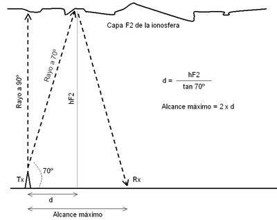
Fig.1. Diagram of a NVIS radio link
The NVIS antenna radiates in the whole region between 70 and 90 degrees of elevation. With the first reflection on the ionosphere, which takes place in the F2 layer, the radio coverage area will spread from the transmitter station to a maximum reach point which may be calculated using trigonometry.
We do know the takeoff angle which provides the maximum range, being 70 degrees. The distance "d" is unknown, but we know that it is the half part of the maximum range. In order to solve the equation, we need a second data: the height at which the reflection in the F2 layer takes place. This height, named "hF2", is being continuously measured by ionosonde stations spread all around the world and is subject to variations mainly with the hour of the day. In the figure 2, it is shown the data collected by the ionosonde station located at the Ebro Observatory (Tarragona, Spain), during September, 27th, 2008. Click on the image to zoom.

In order to provide an estimation of our coverage range, we will consider the two extreme values of hF2 during this day, being around 150 km of height at night and 310 km during the day. At night, the ionosphere F1 and F2 layers are merged in the F layer, which also allows NVIS communications.
If we put those values in the formula shown in the figure 1, we will have maximum ranges between 110 km and 225 km. Depending on the period of time taken into account, the height hF2 may reach up to 400 km, providing radio coverages of up to 300 km, considering an antenna with the indicated takeoff angles.
That is, our NVIS system allows to establish HF communications in a range of up to 300 km around the transmitter station, or even longer, without skip zones. This kind of communications are usually established with only one ionospheric hop and the required power levels are low, normally being enough with 20 W or even less.
3. How to choose the working frequency.
The selection of an appropiated working frequency is essential for a successful operation in NVIS. As a general rule, we will choose a frequency 10% below the ionosphere's F2 layer critical frequency (foF2) at a given time.It is of particular importance not to confuse the foF2 with the MUF. The critical frequency foF2 is the maximum frequency that a radio wave can have in order to be reflected in the F2 layer when arriving at this layer with an angle of incidence of 90 degrees (perpendicular). In the MUF, angles of incidence different of 90 degrees are considered, which practically means that a different MUF will exist for each distance of a HF radio link.
Our goal now is to get foF2 forecasts or, much better, real time measurements of the foF2 made with an ionosonde nearby our transmitter station at a close time. Let's not forget that the foF2 has significant changes over the day and also that it will be different depending on the transmitter location.
In order to get this data, we can check the web site of the Mass Lowel University Center for Atmospheric Research (Massachussetts, USA), where there is a record of foF2 values (among other parameters) measured by ionosondes all around the world.
http://ulcar.uml.edu/stationmap.html
For the particular case of Spain, there are two ionosonde stations offering data to the public, one located at the Ebro Observatory (Roquetes, Tarragona) and the other at the National Institute for Aerospace Technology facilities at El Arenosillo (Huelva).
Ionosonde stations provide special graphs named ionograms, as the one shown in the figure 3. Click on the image to zoom.
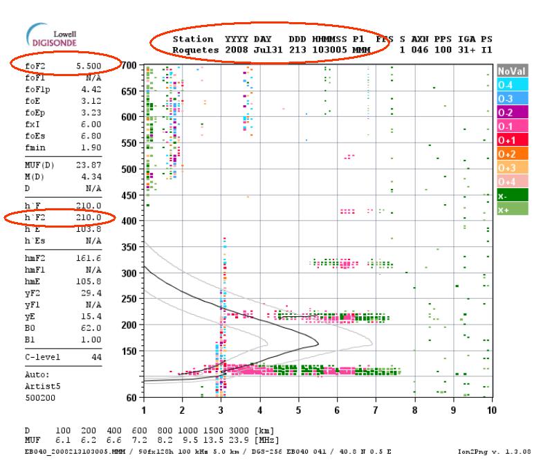
Fig.3. How to pick up the critical frequency foF2 from an ionogram.
In the upper part of the ionogram we can check the hour and date of the measurement, being in the example "2008 Jul31 103005", that is, 31st July 2008 at 10:30 UTC.
In the same upper part, on the left we can see the measured value of the foF2 at this particular time, being 5,500 MHz in the example. If we want to evaluate our communications range, we can read also the value of the height hF2, being 210 km in the example.
Putting into practice our 10% rule, if the foF2 has a value of 5,500 MHz, our NVIS optimal working frequency will be 4,950 MHz at this particular time of day.
Once completed the calculations, we may have the problem of not being authorized to transmit in this particular frequency, as it may occur within the Amateur Radio Service, or even that this frequency is already in use by other stations or with high noise or interference level. In this cases, we will choose a frequency of an authorized band just below the calculated frequency and as near as possible. Never select a frequency above the foF2 because there will not be ionospheric reflection.
4. NVIS antennas.
Apart from choosing a proper working frequency, the other critical point is having an antenna with NVIS capabilities, that is, having a radiation pattern with a main lobe between 70 and 90 degrees of elevation over the ground plane.One possible option is to purchase an antenna especially designed for NVIS, but it is necessary to take into account that such models are normally manufactured for military use only.
Other interesting option is to take advantage of some of the antennas that we normally use for DX communications in HF.
4.1. Base station antennas.
There are a lot of antenna designs to work in NVIS. We will focus in the simpler NVIS antenna for base stations or field operations ever built: the horizontal dipole (figure 4). The same dipole we use for DX. As we will see, the key factor is the height at which we must install the dipole over the ground.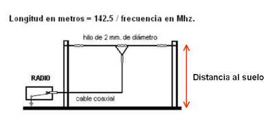
Fig.4. Horizontal wire dipole.
The radiation pattern of an horizontal wire dipole is different as a function of its distance to the ground plane, something which may be easily checked with simulation software such as NTIA/ITS HFAnt.
In the hypothetical and theoretical case of having a dipole installed at one wavelength over ground (at a height of 43 meters if the dipole is for the 7 MHz band), the radiation pattern in elevation will be as the one shown in the figure 5, presenting two main radiation lobes with low takeoff angles. Click on the image to zoom.

Fig.5. Horizontal dipole placed a one wavelength over the ground.
If we put the dipole down to a more appropiate height over ground for installation purposes, let's say to a quarter of the working wavelength (10 meters for a dipole cut for 7 MHz), the radiation pattern in elevation will show one main lobe with its maximun gain located at a takeoff angle of 49 degrees, as shown in the figure 6. The radiation perpendicular to the ground plane is also good, so this installation could be used for NVIS operations. Click on the image to zoom.

Fig.6. Horizontal dipole placed a one quarter wavelength over the ground.
If we continue performing tests and we place the dipole lower and lower, we will check that the radiation pattern rises, up to a point at an exact height of the dipole of one tenth of the working wavelength (4 meters for a dipole for 7 MHz), where the radiation maximum is located at a takeoff angle of 90 degrees, perpendicular to the ground plane, as shown in the figure 7.
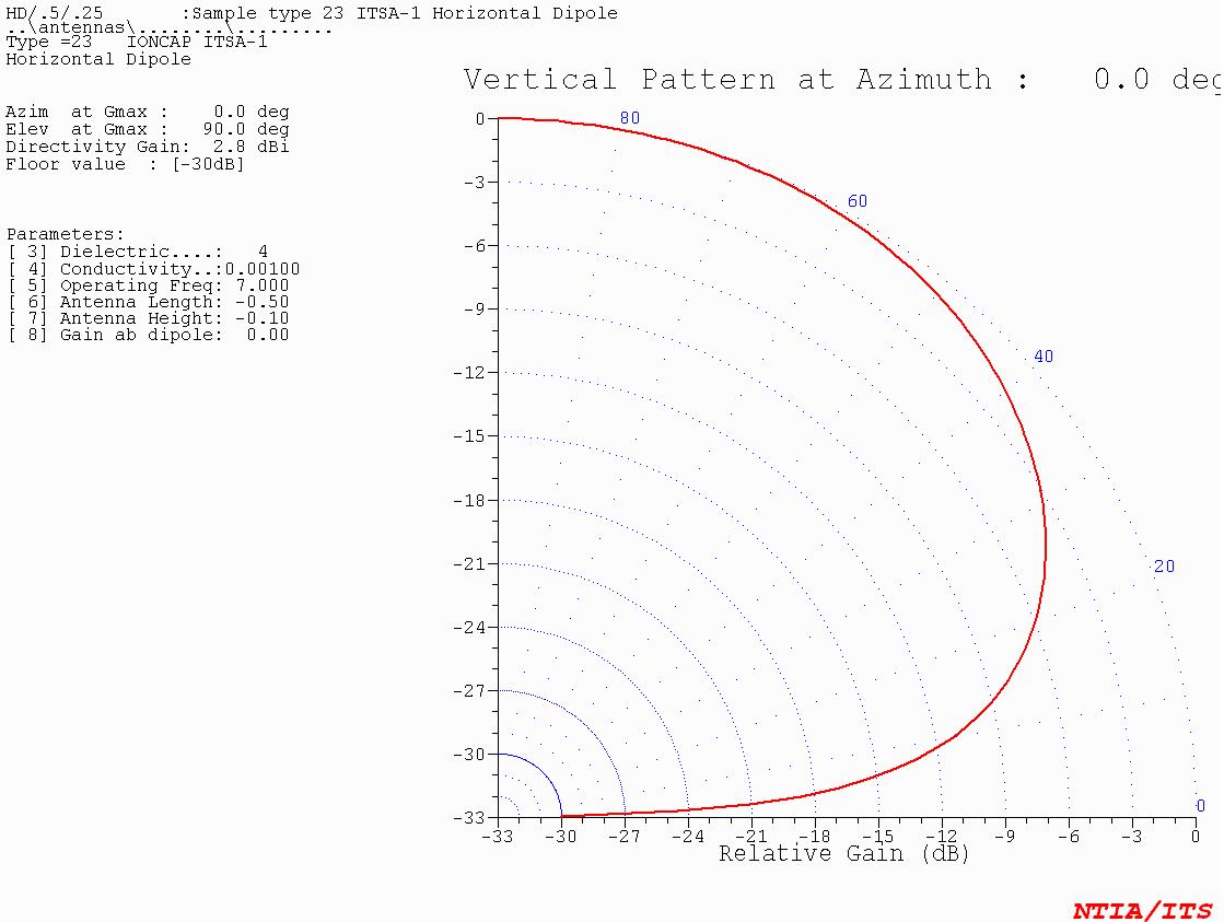
Fig.7. Horizontal dipole placed on 1/10 wavelength over the ground.
If we consider the -3 dB bandwidth, our dipole will be radiating mainly between 30 and 90 degrees in elevation, making this configuration ideal for NVIS operations.
If we continue lowering the dipole, the effect is that the radiation pattern will be more and more high and narrow, losing effectivity in the direction perpendicular to the ground plane. One possible solution should be installing a second conductor wire near the ground plane, as a reflector.
Obviously, the electrical conductivity of the terrain will also have an influence in our antenna. Some authors state that the better distance over the ground to place the dipole is between 0,15 and 0,25 times the working wavelength.
In the design process of a NVIS antenna, we need to take into account that, besides the imposed need of radiating as much vertical as possible, we need to avoid secondary radiation lobes at low takeoff angles due to the fact that they may generate a ground wave of enough intensity to interfere with the reflected skywave in areas near the transmitter station.
4.2. Antennas for mobile communications.
For mobile communications, that is, with the HF radios installed in vehicles, we have two options.The quickest option is using a common vertical antenna and bend it until it is parallel to the ground plane. It will be difficult to achieve the required distance to this plane, but an approximation could provide radiation patterns good enough to work in NVIS.
The other option is having an antenna specifically designed for NVIS. One of the most used antennas for this purpose is the magnetic half-loop, which can be installed on the roof of a vehicle. In the figure 8 a diagram of this type of antenna is shown, designed with the software MMANA-GAL.
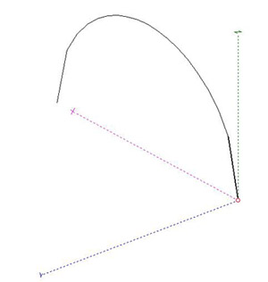
Fig.8. NVIS half-loop antenna.
Those antennas are normally fed from the transceiver by one of its ends and have the peculiarity of having the other end connected to ground. This way, a virtual full loop is built, whose behaviour is mainly magnetic. The radius of the arch is around 1,5 meters.
The great advantage with respect to other NVIS antennas is that the half-loop has an omnidirectional radiation pattern, as shown in the figure 9, making this antenna quite convenient for communications on the move.
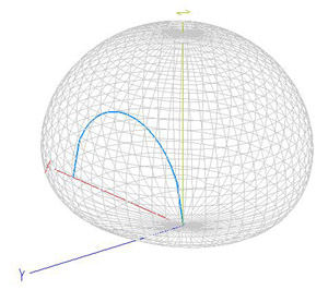
Fig.9. Radiation pattern of a half-loop NVIS antenna.
Another great advantage is the magnetic behaviour, quite similar to the one of the full loop antennas, providing a high Q factor which helps to minimize noise and interferences.
However, this kind of antennas has two important problems: first, the radiation pattern is no more as the one shown in the figure when installing the antenna on top of a vehicle, being distorted mainly backwards, and in the other hand it may have a very high capacitive impedance which may be difficult to match at some frequencies. Besides, the efficiency of radiation is quite low and the antenna has a negative gain (losses).
5. Conclusions.
NVIS communications allow to establish radio links in the HF bands at ranges of up to 300 km without shadow areas, covering the gap existing between the maximum range of VHF/UHF systems and the skip zone of the first hop in DX communications in the HF band. This fact makes NVIS a suitable mode for emergency operations, being its use quite extensive both in those environments and among the military.In order to operate in NVIS we must take into account two fundamental premises. First, we need to choose an adequate antenna with a radiation pattern of enough elevation, such as a horizontal dipole placed at a height over ground of about one tenth of the working wavelength. It is also necessary to select the proper working frequency, always below the critical frequency of the ionosphere's F2 layer (foF2) and in an optimum way around 10 % below it.
Ismael Pellejero - EA4FSI
original article: http://www.ipellejero.es/hf/NVIS/english.html